A Wedge Anchor is a familiar choice for fastening steel plates, handrails, and equipment to solid concrete. Its expansion clip grips the drilled hole as the nut is tightened. In practice, that means the hole diameter, drilling depth, edge distance, and installation torque all matter. A slightly oversized hole can weaken the connection. A dusty hole can also affect performance.
For technical context, ACI 355.2 sets qualification and testing requirements for post-installed mechanical anchors, while ACI 318 addresses their design in concrete structures. Product-specific ICC-ES evaluation reports can provide tested capacities and installation limits. These are more useful than a single broad market statistic: anchor performance changes with concrete strength, embedment, spacing, and loading. Check the report for the exact anchor and conditions, not just a similar-looking product. Real sites are rarely perfect.
A properly selected Wedge Anchor offers a direct, durable connection, but it is not automatically the right answer for cracked concrete, thin slabs, or every load condition. No source article or verified expert quotation was provided here, so I have not invented a statistic or attributed a quote to a named specialist. That matters. A named quotation should be checked against its original publication before use. The practical lesson is simple: match the anchor to the design, then install it to the manufacturer’s instructions.
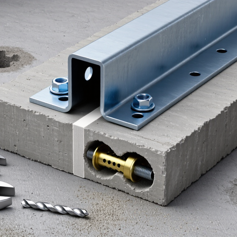
A wedge anchor secures an object by expanding inside a drilled concrete hole. Tightening the nut pulls the anchor’s tapered end into an expansion clip. The clip presses outward against the hole wall, creating a mechanical hold. The fixture sits firm. But only when installation is right.
The load path runs from the attached plate, through the nut and anchor, into the surrounding concrete. ACI 355.2-22 qualification testing evaluates mechanical anchors under tension and shear, including conditions involving cracked concrete. ICC-ES AC193 likewise sets performance tests for mechanical anchors in concrete. These evaluations measure load capacity and installation sensitivity; they do not provide one safe load for every job. Concrete strength, embedment depth, hole cleanliness, edge distance, and anchor spacing all matter. A dusty hole can reduce contact. A hole too close to an edge can raise the risk of concrete failure. Check the anchor’s evaluation data and installation instructions, then match them to the actual concrete and load. Even a solid-looking installation deserves a second look.
Wedge anchors suit solid, sound concrete where a mechanical expansion connection is needed. As the nut tightens, the anchor’s clip presses against the sides of its drilled hole. This works best when the concrete can resist that outward pressure. Not every slab qualifies. Weak, crumbling, or badly spalled areas can compromise the hold.
Check the concrete thickness, edge distance, and spacing before drilling. A hole too close to a slab edge may cause cracking or breakout, especially under heavy loads. For cracked concrete, overhead work, or significant vibration, use an anchor specifically approved for those conditions and follow its design requirements. Wedge anchors are generally intended for solid concrete, not brick, block, or thin toppings over another material.
Installation quality matters. Drill to the specified diameter and embedment depth, then clean the hole as directed; dust can interfere with proper seating. Tighten the nut to the specified torque rather than guessing with a long wrench. On a real job, edges may be chipped and slab thickness uncertain. Pause and verify those details instead of assuming the drawing matches the concrete.
Wedge anchors are useful when a structural fixing needs a firm hold in solid concrete. Tightening the nut pulls the anchor upward, forcing its expansion clip against the drilled hole. The result is a mechanical grip that can suit base plates, handrails, and equipment supports. Installation is straightforward, but precision matters: hole diameter, embedment depth, edge distance, and tightening torque all affect performance.
Concrete strength varies. The National Ready Mixed Concrete Association’s CIP 35, Concrete Tests, describes specified strengths ranging from about 2,500 psi in some residential work to 4,000 psi or higher in commercial construction. That range is not an anchor capacity rating.
The International Code Council Evaluation Service’s AC193 acceptance criteria assess mechanical anchors through testing for conditions including tension, shear, and cracked concrete. Check the anchor’s approved data for the actual load, concrete condition, and installation requirements. Dust left in a hole can undermine a careful installation. I would not assume that a larger anchor automatically means a safer fixing; the supporting concrete and edge distances matter just as much.
Why Choose Wedge Anchors for Concrete?
Installation Steps for Reliable Anchor Performance
Wedge anchors can provide a strong mechanical hold in sound, solid concrete when selected and installed correctly. Start by checking the fixture’s load needs, concrete thickness, and anchor specifications. Confirm the required diameter, embedment depth, and edge spacing. A suitable anchor cannot compensate for weak or damaged concrete. If the slab is cracked, use an anchor specifically rated for that condition.
Mark each hole carefully. Drill perpendicular to the surface with the specified carbide bit, keeping the hole deep enough for the anchor and drilling dust. Clean it using the method recommended for the anchor; dust left inside can interfere with seating. Small details matter. Insert the anchor through the fixture, then tap it gently until the washer and nut sit in place. Tighten to the specified torque with a calibrated wrench, rather than guessing by feel. Too much force can damage the connection. Check that the fixture sits flat and does not shift. It is tempting to rush cleanup, but that step deserves a second look. If the anchor spins, the hole is oversized, or the concrete chips, stop and reassess instead of forcing the installation.
Matching the drill-bit diameter to the nominal anchor diameter is a key step when installing standard wedge anchors.
The chart shows common anchor sizes in millimeters. Drill the hole to the specified depth, remove concrete dust, insert the anchor, and tighten it to the manufacturer’s specified torque. Always check the product instructions and concrete requirements.
Wedge anchors are a strong choice when a fixture must be secured directly to sound, solid concrete. Their expansion clip presses against the sides of a drilled hole as the nut is tightened, creating a firm mechanical hold. Think guardrails, steel base plates, or equipment feet that need dependable resistance to pullout and movement.
Choose them over concrete screws when the connection needs a robust, permanent fixing and the concrete provides enough thickness and edge distance. They can also suit heavier loads better than many light-duty fasteners, provided the anchor’s published capacity matches the job. Good concrete matters. In cracked concrete, near an edge, or where vibration is expected, check the anchor’s rating and the design requirements rather than guessing from its diameter.
Wedge anchors are less forgiving than removable screws. The hole must match the specified diameter and depth, and dust should be cleared before installation; otherwise, the anchor may not seat properly. A torque wrench helps avoid under- or overtightening. Not every time. For hollow block, thin slabs, or installations that may need frequent removal, another fastener may be more practical. I’ve seen a small layout error make an otherwise solid anchor unsuitable, so measure spacing and embedment before drilling.
„Thanks to the LUVIR technology, the solder resist process could be switched directly from the previously used mask exposure to direct exposure. As an outstanding digital solution on the market, this technology has been able to demonstrate fast process times and superior quality on our certified conventional ink in production. This allowed us to fully digitize the solder mask process at low cost – without process or ink adjustments. An excellent benefit to our production in Rot am See.“
Ralf Göhringer (Head of Production WE Rot am See)
I would definitely recommend the Limata machine and team for a future company purchase
Michael Greenaway
Compunetics Inc.
“The Limata ldi has been amazing!! Best thing we did was buy this machine”
Richard Brady
GM
Circuitlabs
“Since 2019, we have been running the Limata X1000 LDI system (including LUVIR for solder mask imaging) in daily production as an addition to our current process with film. The machine was capable of properly exposing Taiyo PSR-4000 BN (DI) solder mask types on normal to high-copper boards using a new and unique direct imaging process. The machine operating interface is very user friendly which allowed for a quick technical training curve. The pre-registration processing reduced several seconds of production time at every print. Limata support and service staff is incomparable. They supported our team every step of the way at basically any time of the day or night, with literally, an immediate response time, customizing the software interface to best fit our Operations and needs.
We have exposed more than 8,000 prints since end of October, on various solder mask colors and some resist film panels. Limata, has proven to be very capable and innovative. They are a strong contender in the industry.
We have very much enjoyed this project, and working with the team!
Thank you Limata for the continued support and being a part of our growth.”
Bill Sezate
Vice President, GM
Summit Interconnect
As a replacement to our current contact exposure process with film, the LIMATA X2000 system including LUVIR-Technology was capable of properly exposing non-LDI solder mask types using a direct imaging process. The machine offers cutting edge software with a very intuitive operating interface which allowed for quick technician training curve. The dual drawer system combined with pre-registration processing reduced several seconds of production time at every machine cycle. Limata support and service staff is world class. They added software patches to keep production running at shortest possible response times, customized the software interface to best fit our in-house Operations system, and even wrote a step-by-step machine processing manual. As a result of the project, we have exposed more than 16,000 times on various product types and solder mask brands/colors. Limata, in a very short timeframe as a company, has definitely shown they are truly innovative and will be challenging the industry of direct imaging for the top spot.
Kevin Beattie
Process Engineer
TTM Technologies
Forest Grove Division