In a process plant, a control signal may call for a valve to open halfway, yet the valve does not always move there smoothly. Friction in the stem, changing air pressure, or load on the actuator can leave the actual position short of the target. A Valve Positioner helps close that gap. It compares the requested position with feedback from the valve, then adjusts actuator pressure to bring the valve closer to the setpoint. Small device. Big effect.
This article explains why a positioner is used, how it supports more accurate control, and where its limits matter. In the field, the difference can show up as steadier flow through a pipe or less hunting in a control loop. Some models also provide diagnostics, but available features vary. A positioner cannot correct every problem: a sticking valve, poor sizing, or incorrect tuning may still require attention. It is tempting to treat the instrument as a simple add-on. That can be misleading. Its performance depends on the valve, actuator, signal, and installation working together. Understanding that relationship helps engineers and technicians choose, commission, and maintain equipment with greater confidence.
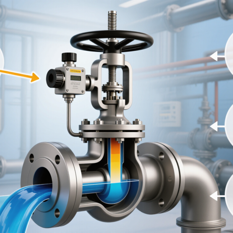
A valve positioner is the feedback link between a control signal and a valve’s actual movement. The controller requests a position; the positioner measures the stem or shaft and adjusts air to the actuator until the two agree. On a pneumatic valve, you may hear a brief hiss as the output changes. That small correction matters.
Without position feedback, friction, changing supply pressure, or actuator load can leave the valve short of its target. A positioner helps the valve follow changing commands more consistently, especially when the packing is tight or process conditions shift. It does not fix everything. A sticking stem or poorly sized valve still needs attention.
Digital models may also record travel and flag unusual behavior, depending on their features and setup. These details can help maintenance teams investigate before a control problem becomes a larger process issue. The International Energy Agency’s Energy Efficiency 2023 report estimates that industry uses about 37% of global energy. That figure is not a claim that positioners alone save energy; it shows why dependable control matters in energy-intensive operations. A positioner can improve command tracking, but its real performance depends on correct installation, calibration, and maintenance. And sometimes, the signal looks fine while the valve still tells another story.
A valve positioner translates a controller’s command into accurate valve travel. With a 4–20 mA input, 4 mA commonly represents 0% travel and 20 mA represents 100%. That gives a 16 mA working span. The electrical convention is covered by ANSI/ISA-50.1, which addresses compatibility of analog signals for process instruments. A pneumatic positioner may instead receive a 3–15 psi signal, a 12 psi span. It compares the command with stem or shaft feedback, then adjusts actuator pressure until the valve reaches the requested position. That sounds simple. Friction, changing process loads, and loose feedback linkages can still cause position errors.
A positioner does not always make travel proportional to the input. The controller or positioner may apply a configured characteristic, such as equal-percentage response, to suit the valve and process. IEC 60534-2-1 provides standardized methods for calculating control-valve flow capacity; it is useful context, but it does not guarantee a particular signal-to-travel response. In the field, verify calibration against actual stem travel, not just the displayed signal. A valve showing 12 mA may not sit at exactly 50% if its range or characterization has been changed.
Tips: Check signal type, configured zero and span, and feedback linkage before troubleshooting the controller. For a 3–15 psi loop, measure pressure at the positioner inlet; for 4–20 mA, confirm loop current under load. Record the as-found readings. Small setup errors matter.
A valve positioner compares the controller’s demand with actual stem travel, then adjusts actuator pressure to reduce the difference. If the signal requests 40% travel but friction leaves the stem at 34%, stem feedback reveals the six-point error. The positioner responds until measured travel approaches the command. That correction repeats across the full 0–100% stroke, not just at the endpoints.
This is important because equal travel changes do not always produce equal flow changes. IEC 60534-2-1 distinguishes a valve’s inherent flow characteristic from its installed behavior, so stem position alone cannot guarantee a particular flow rate. In practice, technicians check feedback linkage, calibration, and full-stroke movement; a loose connection can make the positioner “correct” the wrong measurement. Small errors accumulate. A useful diagnostic is to compare commanded and measured travel at several points, such as 10%, 50%, and 90%, rather than checking only fully open and closed. Those checkpoints are practical checks, not a substitute for the applicable performance test. The feedback loop is powerful, but it cannot fix a sticking stem or poor valve sizing. It is easy to overestimate what calibration alone can repair.
A valve positioner helps the valve stem reach the requested position despite friction, hysteresis, and changing process forces. Without one, packing friction may hold the stem still as the control signal changes. Then the stem can jump, overshoot, and settle late. That is not small. In a steam line, for example, a small pressure change can push against the plug while sticky packing resists movement.
A 2005 review by Choudhury, Thornhill, and Shah in the Journal of Process Control cites estimates that valve problems cause oscillation in 20–30% of industrial control loops. A positioner compares the requested travel with measured stem travel, then adjusts actuator pressure to reduce the difference. It can improve response when friction or load changes interfere, though it cannot repair worn packing or a damaged valve. The distinction matters during troubleshooting.
ANSI/ISA-75.25.01 sets out methods for measuring control-valve response, including dead band and hysteresis. These measures help engineers separate positioner performance from mechanical problems. In practice, check stem movement and air supply under operating conditions; a bench test may miss forces present in the process. Calibration helps, but it is not a cure-all. An imperfect valve can still behave badly.
How Positioner Types and Diagnostics Support Different Applications
A positioner compares the controller’s signal with the valve stem’s actual travel, then adjusts actuator pressure to reduce the difference. In a throttling loop, that correction helps a valve reach the requested position despite friction, changing pressure, or a heavy actuator. Pneumatic positioners suit simple installations; electro-pneumatic models accept electrical control signals, while digital positioners add configuration and diagnostic functions. The choice depends on the process, not just the instrument list.
Diagnostics are useful when access is difficult or valve behavior changes gradually. Digital devices can reveal travel deviation, response problems, and friction trends, helping maintenance teams decide whether to inspect a valve. FieldComm Group has reported more than 40 million installed HART-enabled devices worldwide, illustrating the scale of access to digital field data. That figure does not mean every device provides the same diagnostic coverage. Verify supported alerts and confirm them against operating conditions.
Tips: Match diagnostics to the failure you need to detect. Check air quality, actuator sizing, and feedback linkage during commissioning. A positioner cannot fix a sticking valve; and a diagnostic alarm may need field verification. That distinction matters.
„Thanks to the LUVIR technology, the solder resist process could be switched directly from the previously used mask exposure to direct exposure. As an outstanding digital solution on the market, this technology has been able to demonstrate fast process times and superior quality on our certified conventional ink in production. This allowed us to fully digitize the solder mask process at low cost – without process or ink adjustments. An excellent benefit to our production in Rot am See.“
Ralf Göhringer (Head of Production WE Rot am See)
I would definitely recommend the Limata machine and team for a future company purchase
Michael Greenaway
Compunetics Inc.
“The Limata ldi has been amazing!! Best thing we did was buy this machine”
Richard Brady
GM
Circuitlabs
“Since 2019, we have been running the Limata X1000 LDI system (including LUVIR for solder mask imaging) in daily production as an addition to our current process with film. The machine was capable of properly exposing Taiyo PSR-4000 BN (DI) solder mask types on normal to high-copper boards using a new and unique direct imaging process. The machine operating interface is very user friendly which allowed for a quick technical training curve. The pre-registration processing reduced several seconds of production time at every print. Limata support and service staff is incomparable. They supported our team every step of the way at basically any time of the day or night, with literally, an immediate response time, customizing the software interface to best fit our Operations and needs.
We have exposed more than 8,000 prints since end of October, on various solder mask colors and some resist film panels. Limata, has proven to be very capable and innovative. They are a strong contender in the industry.
We have very much enjoyed this project, and working with the team!
Thank you Limata for the continued support and being a part of our growth.”
Bill Sezate
Vice President, GM
Summit Interconnect
As a replacement to our current contact exposure process with film, the LIMATA X2000 system including LUVIR-Technology was capable of properly exposing non-LDI solder mask types using a direct imaging process. The machine offers cutting edge software with a very intuitive operating interface which allowed for quick technician training curve. The dual drawer system combined with pre-registration processing reduced several seconds of production time at every machine cycle. Limata support and service staff is world class. They added software patches to keep production running at shortest possible response times, customized the software interface to best fit our in-house Operations system, and even wrote a step-by-step machine processing manual. As a result of the project, we have exposed more than 16,000 times on various product types and solder mask brands/colors. Limata, in a very short timeframe as a company, has definitely shown they are truly innovative and will be challenging the industry of direct imaging for the top spot.
Kevin Beattie
Process Engineer
TTM Technologies
Forest Grove Division