Why Are Robotic Gears Essential for Automation? The answer begins with motion. A robotic arm may look smooth as it lifts a metal component, but every turn depends on controlled force and precise transmission. A Robotic Gear transfers motor power to the joint, helping the machine move accurately, carry loads, and repeat tasks across long production shifts.
Robotics researcher Dr. Sami Haddadin’s work emphasizes safe, predictable interaction between robots and people. A fair paraphrase of that principle is: “Reliable motion matters only when people can predict it.” Gear selection supports that goal. Engineers consider torque, speed, backlash, heat, noise, and service life—not just the gear’s size. Small errors matter. A fraction of a degree can affect a gripper’s placement or a tool’s path. In a factory, poor gear matching may also cause vibration, wear, and costly downtime.
This introduction sets up the key themes: how gears transmit motion, which gear types suit different robotic joints, and how design choices influence precision and durability. It will also consider real trade-offs. Higher precision can raise cost, while compact components may leave less room for cooling or maintenance. No gear is perfect. The right choice depends on the robot, its task, and the conditions it must handle.
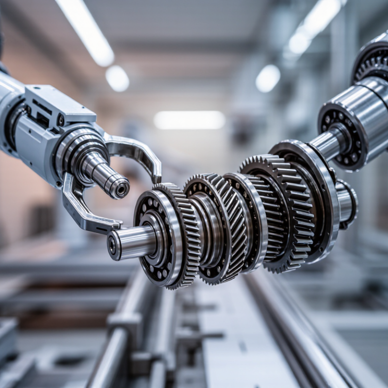
A robotic gear is a mechanical link between a motor and a moving joint. It changes speed and torque, helping a small motor lift or position a heavier load. Inside a joint, a reduction gear trades fast rotation for greater turning force. Encoders measure position, while a controller adjusts the motor to reach the target. Small parts matter. A little backlash can make a robot’s gripper miss a narrow pick point or leave a seam uneven.
Common designs include planetary, harmonic, and cycloidal gears. Planetary units distribute load across several meshing gears; harmonic drives use a flexible element for compact, high-ratio motion. Cycloidal designs can handle impact, though each choice brings trade-offs in size, stiffness, noise, and maintenance. The scale of deployment makes these details practical, not theoretical: the International Federation of Robotics reported 4,281,585 industrial robots operating worldwide in 2023, in World Robotics 2024. Still, gears are not magic. Heat, lubrication, and wear affect performance, and specifications alone cannot predict every real-world result. A technician may need to check vibration and joint play after installation. That work is easy to underestimate.
Why Are Robotic Gears Essential for Automation?
How Gears Control Motion, Speed, and Torque
A robot motor may spin quickly, but its shaft alone often lacks the control needed for careful work. Gears connect the motor to a joint and shape how that joint moves. In a small pick-and-place arm, a reduction gear can turn fast motor rotation into slower, steadier movement. The gripper can then approach a part without rushing past it.
The gear ratio sets the relationship between speed and torque. A higher reduction ratio usually lowers output speed while increasing available torque, helping a joint lift a heavier load. But torque is not free. Gears, bearings, and lubricant create friction, so some input energy becomes heat. That trade-off matters. Designers must match the ratio to the task, motor, and expected load, rather than simply choosing the largest reduction.
Gears also influence positioning accuracy. Backlash—the small clearance between meshing teeth—can cause a joint to shift slightly when direction changes. On a robot placing components into a tray, that movement may affect repeatability. Small errors add up. Careful gear selection, good alignment, and regular inspection help keep motion predictable. Still, gears cannot correct every control problem; software tuning and feedback sensors remain important parts of a dependable motion system.
In a robot arm, gears translate motor rotation into controlled movement at each joint. A reduction gear can trade speed for torque, helping a compact motor lift a heavier load smoothly. That matters when a gripper places a glass vial or aligns a screw with a narrow opening. Small errors matter. Gear geometry and manufacturing tolerances influence backlash, the slight free movement that appears when direction changes. Even a fraction of a degree can shift a tool tip several millimeters at the end of a long arm.
Precision depends on more than a gear’s nominal ratio. Correct alignment, suitable materials, and stable lubrication help keep motion repeatable as temperature and load vary. A gear that runs quietly in a test may develop wear under frequent starts, stops, and reversals. Engineers can monitor noise, heat, vibration, and position error during real work cycles.
No gear stays perfect. In practice, teams sometimes find that a precisely specified gear feels rough after installation. Routine inspection can reveal looseness or damaged teeth before accuracy drops, though maintenance intervals are easy to underestimate. Choosing tighter tolerances may improve control, but can raise cost and sensitivity to assembly errors.
Robotic automation uses several gear types because each handles motion differently. Spur gears are simple, efficient, and easy to inspect. Their straight teeth suit compact conveyors and slower robot joints, though they can become noisy at higher speeds. Helical gears mesh gradually, which often makes them quieter and better suited for smooth, continuous movement.
Space is tight.
Bevel gears transfer rotation between intersecting shafts, often at a right angle. They can help orient a gripper or redirect motion inside a compact assembly. Worm gears also change direction and can provide substantial speed reduction in one stage. However, sliding contact creates heat and friction, so lubrication and operating cycles matter.
Planetary gears place several smaller gears around a central sun gear. This arrangement offers high torque in a compact package, useful in robot joints where room is limited. Rack-and-pinion systems convert rotation into straight-line travel for slides and positioning axes.
The best choice depends on load, speed, accuracy, available space, and duty cycle. A small pick-and-place arm may benefit from a planetary gearbox, while a long linear axis may use a rack and pinion. Harmonic drives can provide high reduction with little backlash, but they are sensitive to operating conditions and can be costly to replace.
Noise matters.
Gear selection is rarely perfect; engineers may trade efficiency for compactness or precision for price. A practical design also leaves access for checking wear and lubricant, details that are easy to overlook on a drawing.
Robotic gears shape how accurately a machine moves, not just how much it can lift. A higher reduction ratio increases output torque while lowering speed. It can also make small motor movements easier to control. But gears are not a free boost: friction and heat reduce usable power.
Small errors matter. Backlash can leave a slight gap between commanded and actual motion, especially when a robot reverses direction. For a pick-and-place arm, that gap may shift a gripper away from a narrow part. Low-backlash gears can improve repeatability, but they may cost more and need careful alignment. Gear stiffness matters too; a flexible transmission can vibrate under a changing load.
The right choice depends on the task. A fast conveyor robot may benefit from compact gearing with enough torque for frequent starts and stops. A precision assembly arm may need low backlash and high torsional stiffness instead. Noise, duty cycle, mounting space, and operating temperature also deserve attention. Heat builds quickly. A gearbox that performs well during a short test may run hot after hours of repeated motion. Engineers should check actual loads and measure position error during commissioning. A neat spreadsheet can still miss cable drag or an unexpectedly heavy tool. Those details sometimes change the gear choice.
How gear selection affects robotic output speed and torque
A higher reduction ratio trades speed for torque, helping a robot move heavier loads or control motion more precisely. This illustrative calculation assumes a motor input of 3,000 rpm and 0.2 N·m, with 90% gear efficiency; actual performance varies with the motor, gearbox, load, and operating conditions.
„Thanks to the LUVIR technology, the solder resist process could be switched directly from the previously used mask exposure to direct exposure. As an outstanding digital solution on the market, this technology has been able to demonstrate fast process times and superior quality on our certified conventional ink in production. This allowed us to fully digitize the solder mask process at low cost – without process or ink adjustments. An excellent benefit to our production in Rot am See.“
Ralf Göhringer (Head of Production WE Rot am See)
I would definitely recommend the Limata machine and team for a future company purchase
Michael Greenaway
Compunetics Inc.
“The Limata ldi has been amazing!! Best thing we did was buy this machine”
Richard Brady
GM
Circuitlabs
“Since 2019, we have been running the Limata X1000 LDI system (including LUVIR for solder mask imaging) in daily production as an addition to our current process with film. The machine was capable of properly exposing Taiyo PSR-4000 BN (DI) solder mask types on normal to high-copper boards using a new and unique direct imaging process. The machine operating interface is very user friendly which allowed for a quick technical training curve. The pre-registration processing reduced several seconds of production time at every print. Limata support and service staff is incomparable. They supported our team every step of the way at basically any time of the day or night, with literally, an immediate response time, customizing the software interface to best fit our Operations and needs.
We have exposed more than 8,000 prints since end of October, on various solder mask colors and some resist film panels. Limata, has proven to be very capable and innovative. They are a strong contender in the industry.
We have very much enjoyed this project, and working with the team!
Thank you Limata for the continued support and being a part of our growth.”
Bill Sezate
Vice President, GM
Summit Interconnect
As a replacement to our current contact exposure process with film, the LIMATA X2000 system including LUVIR-Technology was capable of properly exposing non-LDI solder mask types using a direct imaging process. The machine offers cutting edge software with a very intuitive operating interface which allowed for quick technician training curve. The dual drawer system combined with pre-registration processing reduced several seconds of production time at every machine cycle. Limata support and service staff is world class. They added software patches to keep production running at shortest possible response times, customized the software interface to best fit our in-house Operations system, and even wrote a step-by-step machine processing manual. As a result of the project, we have exposed more than 16,000 times on various product types and solder mask brands/colors. Limata, in a very short timeframe as a company, has definitely shown they are truly innovative and will be challenging the industry of direct imaging for the top spot.
Kevin Beattie
Process Engineer
TTM Technologies
Forest Grove Division
